How Smart Fuel Management Systems Work: Data Connectivity, Flow Monitoring, and Real-Time Visibility
Modern industrial fuel management has moved well beyond manual dip readings and paper reconciliation logs. Today, connected fuel systems combine physical infrastructure — pumps, tanks, and meters — with digital communication layers that deliver real-time visibility from tanker delivery through to final consumption. This article breaks down how that automation chain works, and explores the two primary methods for getting field device data onto your server: MQTT and API Polling.
The Fuel Management Automation Chain
Before diving into data connectivity, it helps to understand the physical and digital layers that make up a complete fuel management system. The two run in parallel — one moves fuel, the other moves data.
Physical Fuel Flow
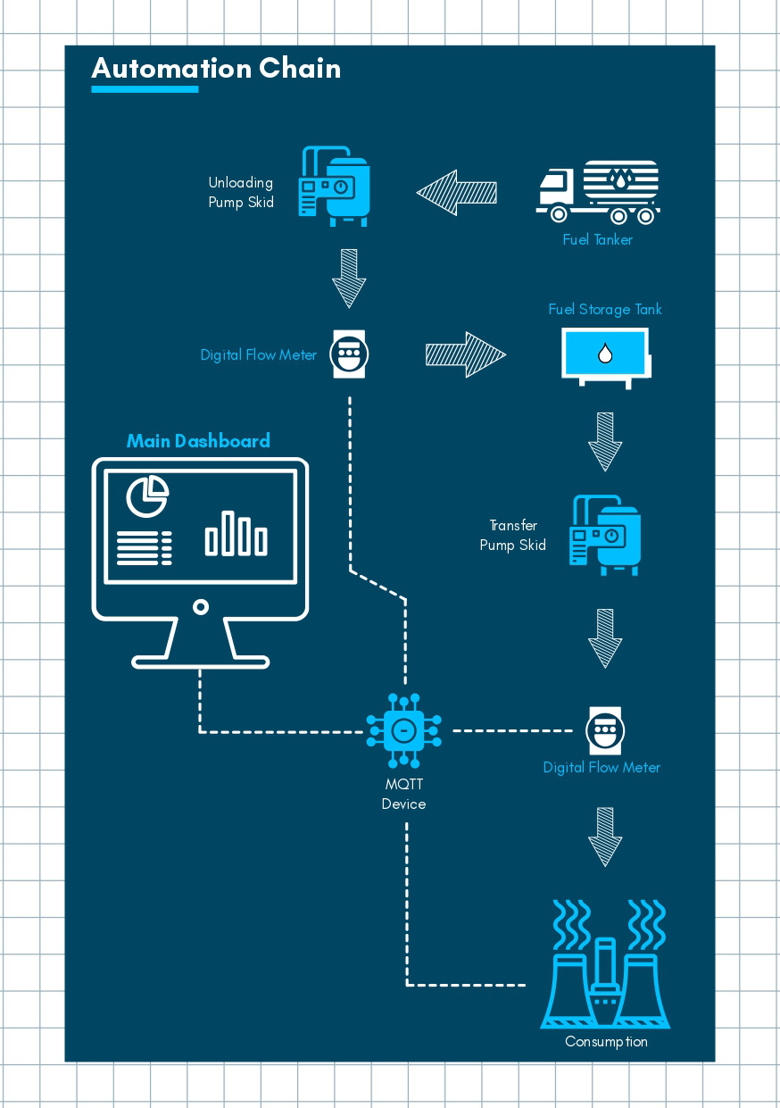
A well-engineered fuel management system follows a clear, linear process:
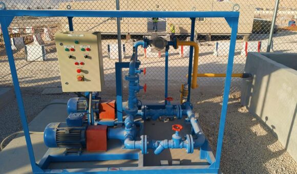
- Fuel Tanker — The entry point. Fuel is delivered to site by road tanker.
- Unloading Pump Skid — Physically moves fuel from the tanker into the storage system.
- Digital Flow Meter (Intake) — Records the precise volume of fuel being received into storage.
- Fuel Storage Tank — The central holding point for the site’s fuel supply.
- Transfer Pump Skid — Moves fuel from storage toward the point of use.
- Digital Flow Meter (Offtake) — Captures the exact volume being drawn for consumption.
- Consumption Point — The final destination: an industrial plant, power generator, or fleet depot.
The placement of meters at both the unloading and transfer stages is deliberate and critical. Two measurement points create a complete accountability chain — any variance between fuel received and fuel consumed can be detected immediately, whether caused by a leak, theft, or metering error.
Digital Monitoring Layer
Running in parallel to the physical flow is an IIoT architecture that provides real-time visibility across the entire chain:
- Both digital flow meters feed data to a central MQTT device, which acts as the communication hub for the system.
- The MQTT device consolidates readings from both the unloading and transfer meters and transmits them to a main dashboard.
- Operators can monitor the entire fuel chain — from delivery through to consumption — on a single interface, in real time.
This dual-layer design means that fuel accountability is no longer a manual, end-of-day reconciliation task. Variances are visible as they happen.
Connecting Field Devices to Your Server: MQTT vs. API Polling
Once your meters and sensors are generating data, the next question is: how does that data get from the field device to your server? There are two primary methods, each with distinct architectural characteristics and trade-offs.
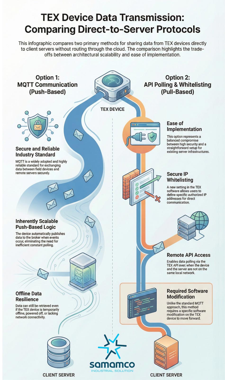
Option 1: MQTT Communication (Push-Based)
MQTT (Message Queuing Telemetry Transport) is a lightweight, widely adopted industry standard for secure data exchange between field devices and remote servers. It operates on a push-based architecture — the device automatically publishes data to a broker when an event occurs, rather than waiting to be asked.
How it works: The TEX device connects to an MQTT broker. When a new flow reading, alarm, or status update is generated, the device publishes it to the broker immediately. The server subscribes to the relevant topics and receives the data in real time.
Key characteristics:
- Event-driven efficiency — Data is only transmitted when something happens, avoiding the overhead of constant polling requests.
- Offline resilience — If the device is temporarily offline, powered down, or experiencing network disruption, data can still be retrieved once connectivity is restored. No readings are lost.
- Scalability — Because devices push data independently, adding more meters or sensors to the network does not create proportional increases in server load.
- Security — MQTT supports TLS encryption and authentication, making it a secure channel for field-to-server communication.
Best suited for: Large-scale operations, multi-site deployments, and environments where network connectivity may be intermittent.
Option 2: API Polling & IP Whitelisting (Pull-Based)
API Polling uses a pull-based architecture — the server periodically sends a request to the TEX device asking for its latest data. The device responds with the requested readings.
How it works: The server is configured to call the TEX device’s API at defined intervals. To control which servers are authorised to query the device, the TEX software includes an IP whitelisting setting — only requests from pre-approved IP addresses are accepted.
Key characteristics:
- Ease of integration — For organisations with existing server infrastructure, API polling can be simpler to implement without needing to set up and manage an MQTT broker.
- IP Whitelisting security — Access is restricted to authorised IP addresses defined directly in the TEX software, providing a straightforward security control.
- Remote access capable — The device and server do not need to be on the same local network, enabling polling from a remote or cloud-based server.
- Software modification required — Unlike the standard MQTT approach, API polling requires a specific software modification on the TEX device before it can be used. This is an important implementation consideration.
Best suited for: Smaller installations or organisations integrating with an existing server infrastructure where a dedicated MQTT broker is not in place.
MQTT vs. API Polling: A Direct Comparison
| MQTT (Push) | API Polling (Pull) | |
|---|---|---|
| Architecture | Push — device sends data automatically | Pull — server requests data on a schedule |
| Efficiency | High — event-driven, no idle polling | Moderate — constant requests regardless of events |
| Offline Resilience | Yes — data recoverable after reconnection | Limited — missed polls may mean lost data |
| Scalability | Excellent for large, multi-device networks | Increases server load as device count grows |
| Setup Complexity | Requires MQTT broker configuration | Simpler for existing server setups |
| Device Modification | Standard — no special modification needed | Required — specific TEX software change needed |
| Security | TLS encryption + authentication | IP whitelisting at device level |
Which Method Should You Choose?
The right choice depends on the scale and nature of your operation.
If you are managing multiple sites, large tank farms, or critical infrastructure where data continuity and resilience are non-negotiable — MQTT is the recommended approach. Its push-based, event-driven model is built for scale and handles connectivity disruption gracefully.
If you have an existing server infrastructure and need a faster path to integration without deploying a new broker — API Polling is a practical starting point, provided you plan for the required device-side software modification and account for its polling overhead as your device count grows.
In many mature fuel management deployments, both methods are used in combination — MQTT as the primary real-time data channel, with API access retained for specific reporting or integration requirements.
The Bottom Line
A well-designed fuel management system is not just about moving fuel efficiently — it is about knowing exactly what is happening at every stage, in real time. By placing digital flow meters at both the unloading and transfer points, and connecting them through a robust IIoT communication layer, operators gain complete accountability across the entire delivery-to-consumption chain.
Whether you implement MQTT or API Polling — or both — the goal is the same: eliminate manual reconciliation, detect variances the moment they occur, and give your operations team the visibility they need to act before small discrepancies become costly problems.
For more information on how Samamco implements connected fuel management systems for industrial clients across Saudi Arabia, contact our team.